

Projects
This page lists in-progress projects which are not complete enough for a full blog post yet.
Power Electronics
Digital Stuff
- STM32 / FPGA Video Dev Board
- Reflow Soldering Test
- Modular DAQ System - Prototype
- Modular DAQ System - Card Rack
- i.MX6 Linux Board
BLDC Motor Controllers
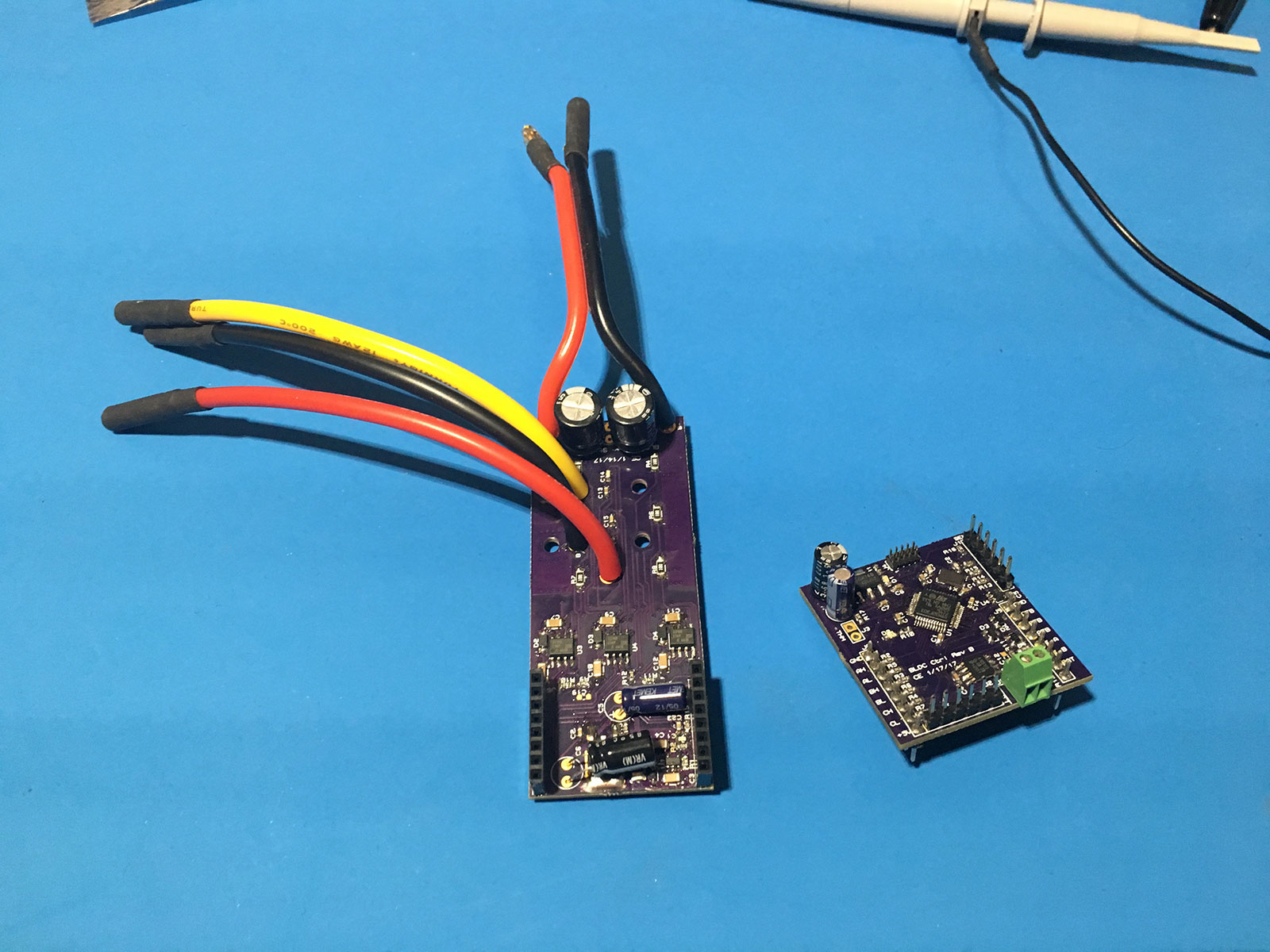
[2/11/2019] I have been experimenting with brushless motor control off and on over the past several years. My first try started with building a 3-phase MOSFET bridge on a breadboard back in 2014. I've gone through several iterations of hardware since then. The first two are shown in the photo below. The left board of the two, paired with an STM32F0 Discovery board for control, was my first version. I was new to surface mount soldering at the time, so it is partially through hole. I made the board on the right after getting tired of the mess of jumper wires. It holds a STM32F3 and mounts directly to the power board.
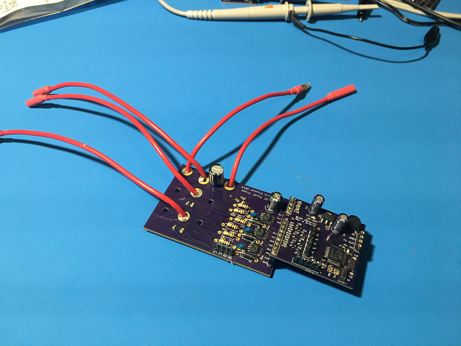
The next version is shown below. It improved the layout and added on-board voltage regulation for gate drive and microcontroller power rails. (previous version required external 12V and 5V supplies)
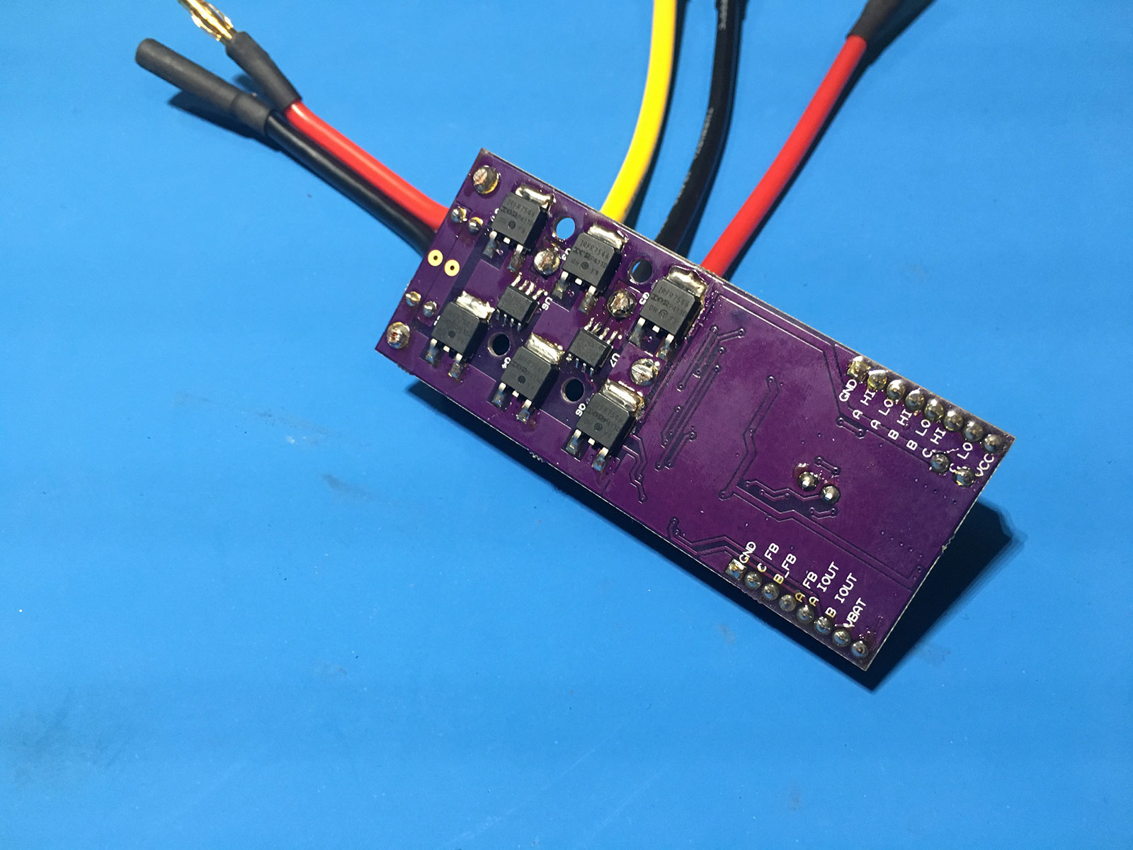
Both of the boards have MOSFETS mounted on the bottom, which is less than ideal. I did this to allow clamping to a heatsink. At the time my PCB knowledge was too limited to make a better design which would pass heat through the board. Two hall effect current sensors are also placed on the bottom to allow measurement of phase currents.
The embedded software running on these controllers communicates with a PC over serial for control. I built a C# program which allows setting of parameters as well as graphing of phase voltage, current, and other internal values.
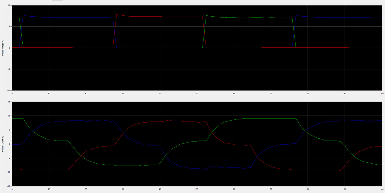
It is currently able to do basic sensorless control or use hall sensors for position feedback. Proper field-oriented control is not far off. I have the necessary PWM scheme in place already and working current feedback. The main holdup at this point is some conflicts between pin assignments for hall sensor inputs and timer channels. I intend to eventually do a new revision with several improvements: more compact layout (and no wires coming out of the middle of the board), better thermal design, and adjusted pin assignments for the microcontroller. This project is mostly on the back burner until I finish a few other things.
High Power Motor Controller
[5/12/2020] I have a working prototype controller. Many changes from the initial design below. Current sense uses a shunt instead of hall sensors, terminals are different, and lots of layout changes. See this twitter thread for more details. I'll do a full blog post on this once I have better software and can do some testing.
[2/22/2019] The purpose of this project is to build a controller for an Etek motor (15HP, 48V DC motor). I got one of these motors from Craigslist back in high school and have wanted to build some kind of electric vehicle with it ever since. At the time, I didn't have the money to buy enough batteries to run it. More recently, time and space have been the limiting factors. I've been considering how to build my own controller for it in order to make an electric motorcycle. This is somewhat of a background project, as I won't have space to seriously work on it until I move to a house with garage space.
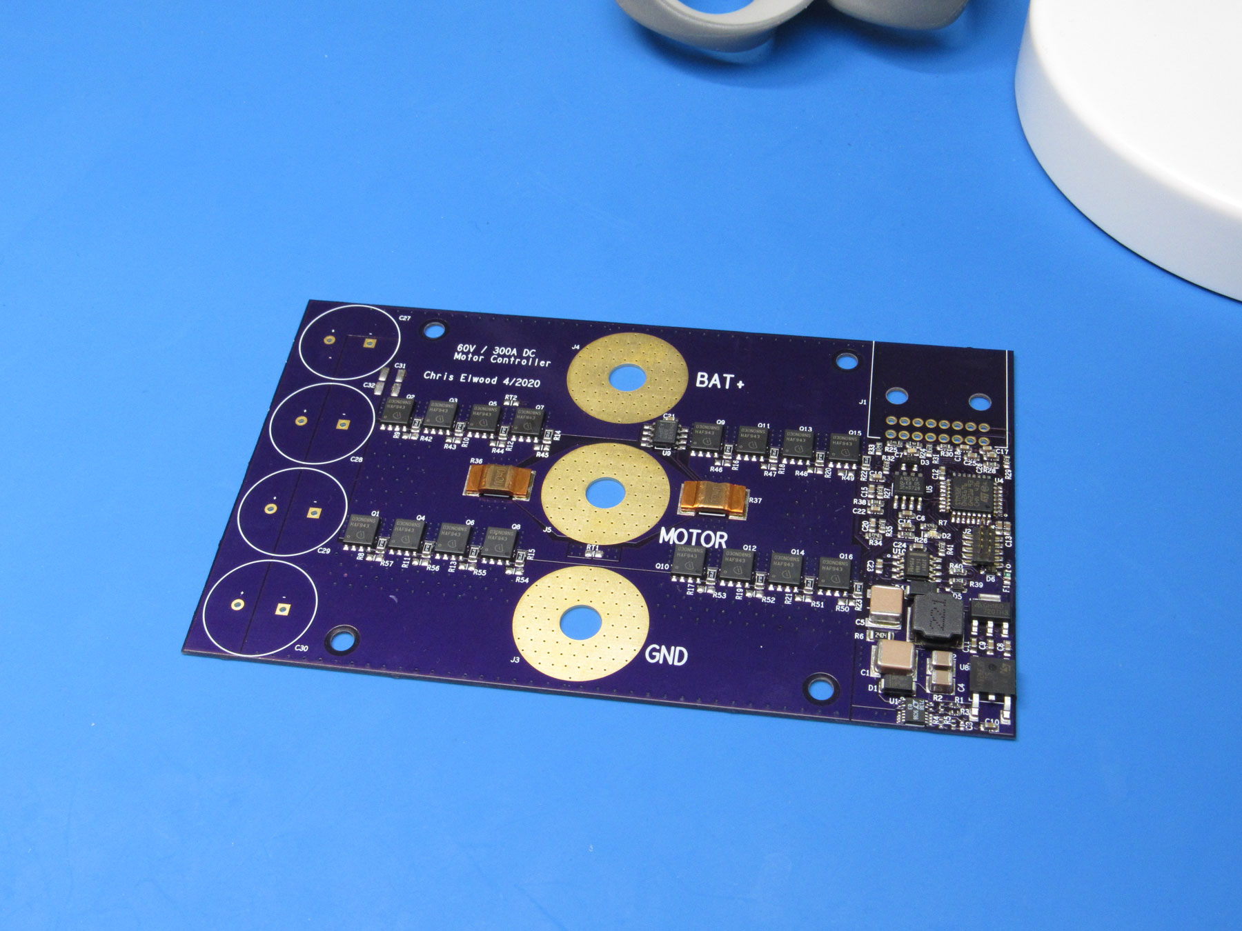
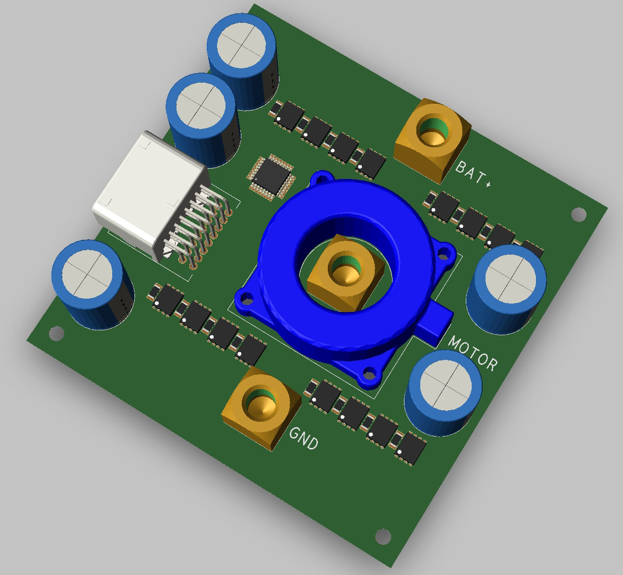
The electronics for the controller will be fairly simple. I only need to run a DC motor in one direction, so it basically consists of a bunch of MOSFETs in parallel along with a microcontroller and driver to switch them. The hard part of this project is designing a PCB to handle the large currents involved. The motor is rated for 150A continuous and up to 300A for 1 minute. Some rough math suggests this is possible with some creative layout on a 4-layer, 2oz copper PCB. This puts it in the realm of prototype PCBs that I can order for a reasonable cost. I've considered several possibilities using bus bars or other methods. My current plan passes all current through the PCB though and uses high current wire-to-board terminals to make the connection to power cables. I had been planning to use a LEM hall effect current sensor (seen in the render below), but it is just too big. It will be replaced by either a different hall sensor design or a resistive shunt.
The image below shows the work in progress rough layout. Only the large components are included right now. Goal is to get everything within a 10cm by 10cm footprint. I'm pretty sure it's doable once I come up with a smaller current sense solution.
Battery Management
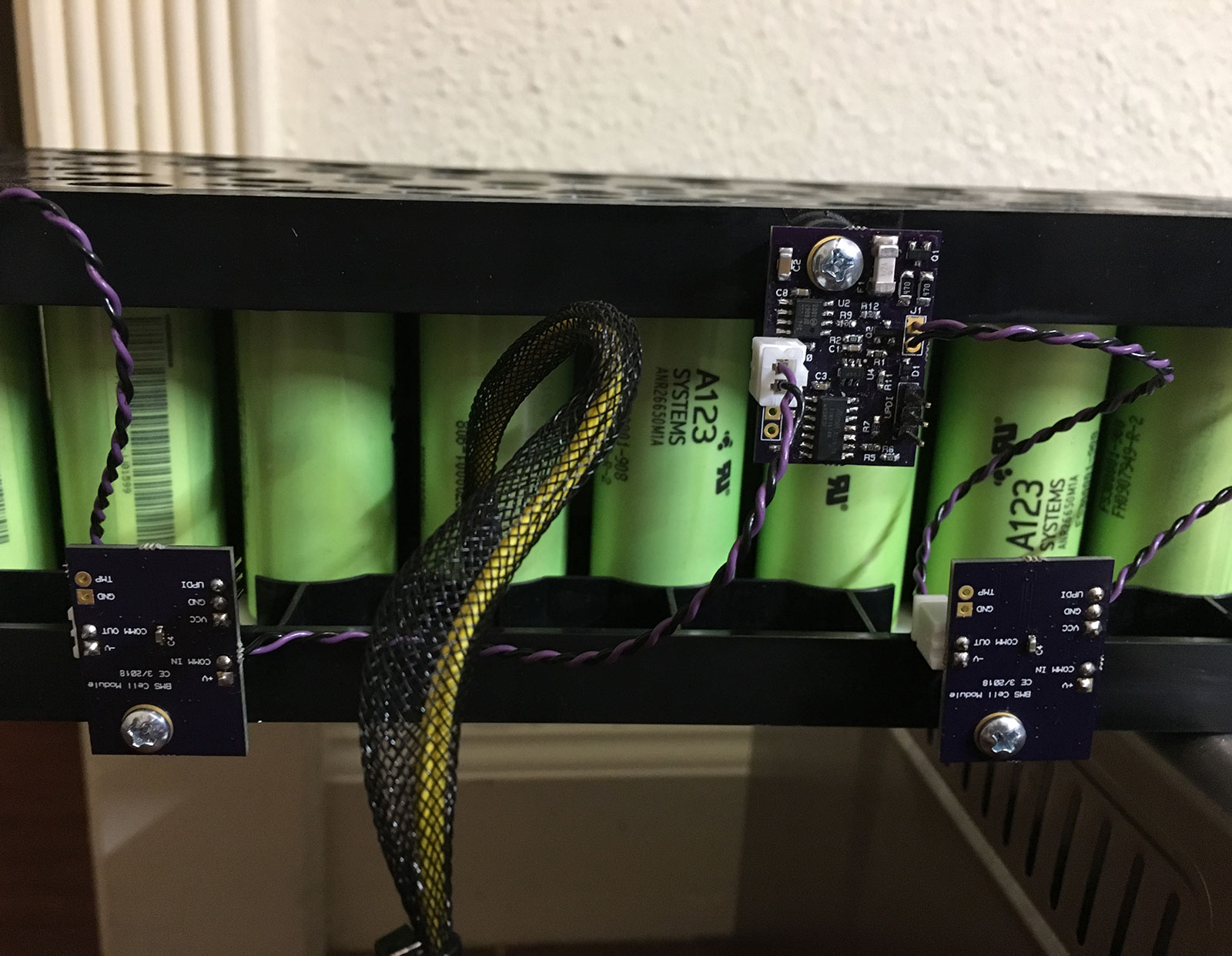
[2/17/2019] The other major component needed to complement a motor controller is some sort of battery pack. I currently have a stack of A123 LiFePO4 battery modules from ebay. These modules include a battery management system (BMS), but with no documentation of its connectors or communication protocol, it is not useful to me. I have been working on a replacement system to monitor and balance cell voltages. It consists of a set of small boards which each monitor one group of parallel cells and communicate over a chain of isolated serial connections. Each board has a small AVR microcontroller plus a an ADC with an accurate voltage reference.
The boards are assembled and ready, but no software has been written yet. That will probably not happen until the motor controller is further along.
There will also be a lot of work involved in repackaging the battery modules to fit into whatever vehicle I end up putting them in. I expect the BMS electronics will need to evolve as the battery form factor changes. The current design is only intended for bench testing using the existing A123 packs as is.
STM32 / FPGA Video Dev Board
[2/13/2019] This project is a small development board with a STM32F4 microcontroller and Spartan-6 FPGA that I built last month to test a few things out. See the full writeup here.

Reflow Soldering Test
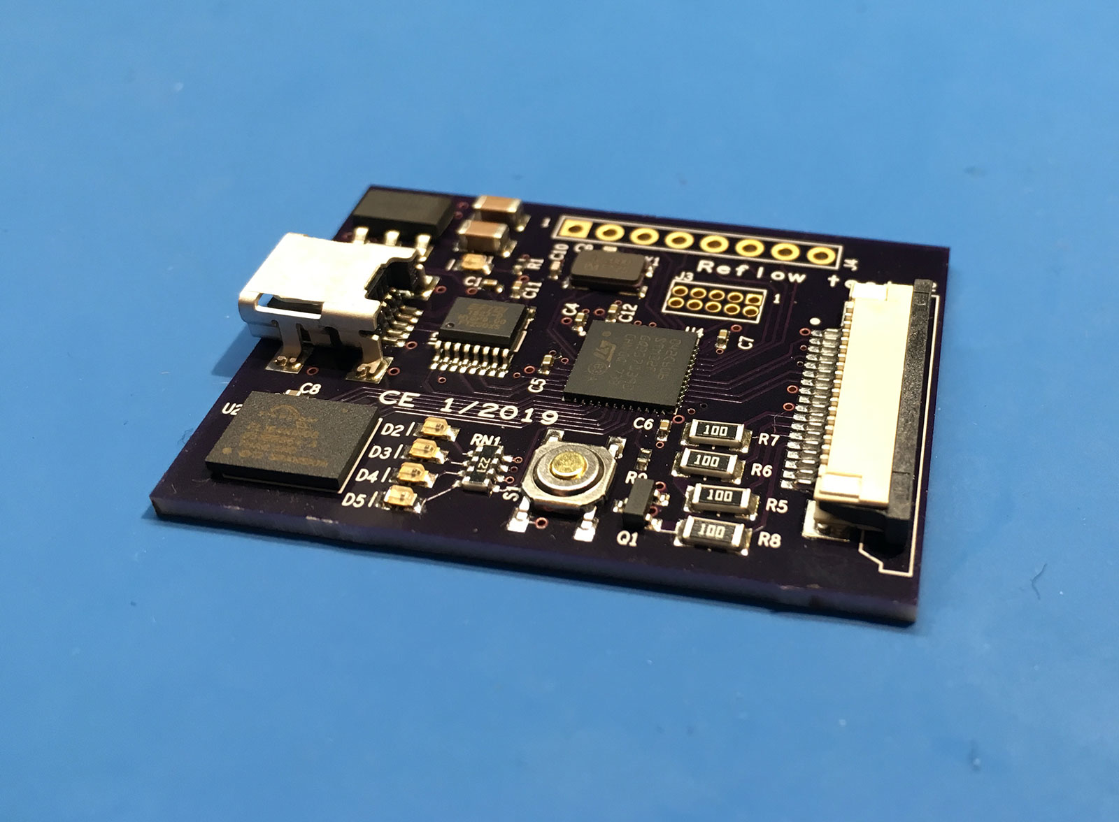
[2/17/2019] These are some test boards I made to see how difficult it would be to solder various components using a reflow process. Includes a QFN, BGA, and 0402 passives.
One of the boards is shown below. I assembled several others to test different reflow profiles and board finishes.
Modular DAQ System - Prototype
[2/22/2019] This is a first prototype of a modular data acquisition (DAQ) system. The idea is to have a main controller which communicates with modules that each provide some type of input or output. I have been working on defining a common interface for cards which allows flexibility for a range of cards from basic, low cost ones up to higher performance ones. The initial application is to allow bench testing of engine control units (ECUs). However, I want the platform to be flexible enough to support cards for general purpose measurement and other future uses.
This initial design uses an FPGA development board as the main controller, with ribbon cables providing a SPI connection to each card. The final version will use a card rack system, as described in the next post below. The photo below shows the current setup with the controller and three modules.
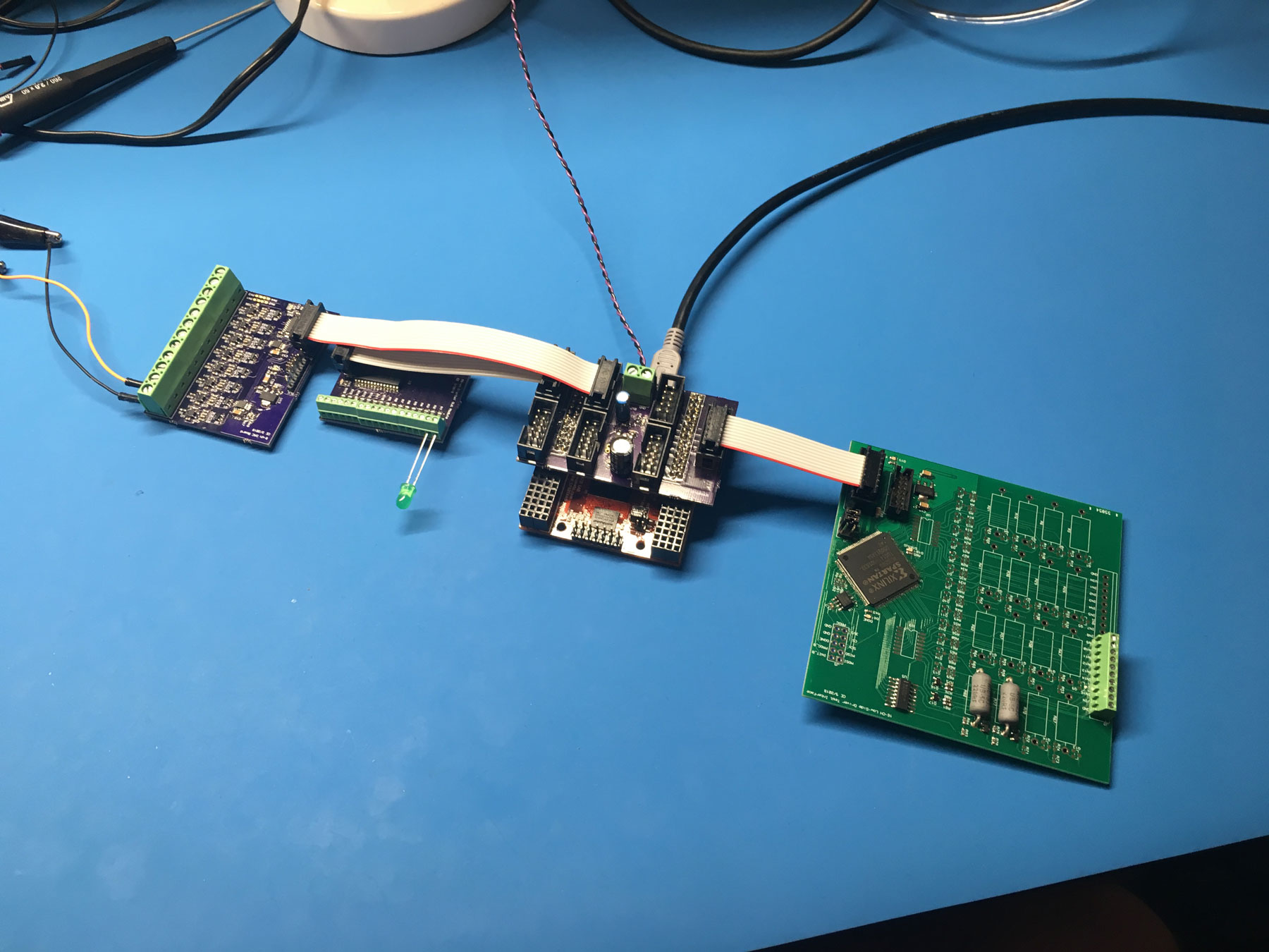
The center device is the controller. It is a Numato Saturn FPGA development board with a breakout that I designed on top. It communicates with the modules over SPI and with the PC over a USB-to-serial connection.
The far left board is an analog output card. It has eight 12-bit analog outputs with software selectable 5V or 30V ranges. The outputs are buffered by LM7321 power opamps to achieve the 0-30V range and drive enough current to handle ECU inputs with strong pull-ups or pull-downs. A STM32F0 microcontroller is used to convert from SPI to the I2C interface used by the DACs. It also offloads scaling and calibration of the outputs from the main controller.
The second board from the left is a digital I/O board. It is simply a MCP23S17 I/O expander. This device provides 16 GPIO pins over an SPI interface, with the only additional hardware being series resistors to protect the outputs.
The board on the right is a partially populated PWM input board. It provides 16 inputs which can measure frequency, duty cycle, and timing of digital signals. It is intended to interface with low side driver outputs on an ECU which would normally drive spark coils, fuel injectors, and other actuators. Therefore, it also has load resistors to bias those low side drivers and simulate the loads which would normally be connected. These are 220 ohm, 5W resistors which can pull each input up to battery voltage (usually 12V or 24V) and are software selectable per input. A Spartan-3 FPGA is used to handle all of this, as there are few microcontrollers with enough timer inputs to handle the 32 channels planned for the final version of this card. It also allows more flexibility for measurements than might be difficult to do using a typical microcontroller.
Currently, I have a PC application which talks to the main board and allows control of all the inputs and outputs. The final controller will have a STM32F7 microcontroller connected to the FPGA (similar architecture to the video dev board I did) to allow a model or other code to run on the system directly.

Modular DAQ System - Card Rack
[10/14/2019] New controller card is done which fits the card rack. I also built a new version of the digital I/O card which fixes the mechanical problems of the first revision. More details to come.
[2/22/2019] While developing software using the prototype DAQ setup descirbed above, I have also been working on the next iteration of the hardware. This consists of a backplane using PCIe connectors and new versions of all the cards which fit this form factor.
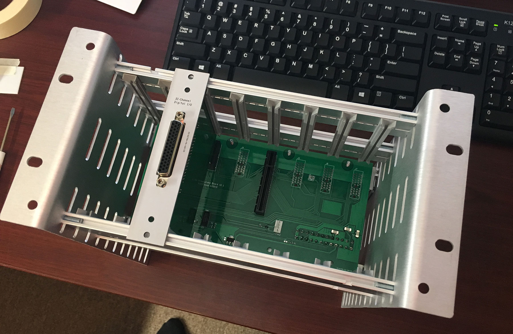
I currently have a completed backplane, which turned out good both mechanically and electrically. It provides one controller slot and seven card slots (although one is narrow due to the width of the card rack). Power comes from a standard PC power supply connected to a Molex connector on the back. There is a STM32F0 microcontroller on the board which manages the power supply, several fan and thermistor connections, and an I2C bus for identifying cards.
The only card I built for this format so far is a digital I/O card. I started with this since it is the simplest/cheapest card, making it a good candidate for testing out mechanical fit of everything. It fits the card slot and PCIe connector, but has issues with alignment of the front panel and connector. Not surprising, given that I rushed this out before Chinese new year.
Next step here is to finsh the new controller I'm designing to fit this backplane. I will also order a fixed version of the digital I/O card. I already have adapter boards to go from 36-pin PCIe to the 10-pin ribbon cables used for the prototype cards. This will allow old cards to be used in this rack until I get all of them updated.
i.MX 6 Linux Board
[4/16/2020] Peripheral testing was mostly successful. Found two issues: The LCD I was planning to use will not work, so I need to find a different one. Also, the way I generate a 3.3V supply from the lipo battery needs to be changed.
[4/7/2020] Most of the schematic is done at this point. I also built up a test board to test out the power management and some peripherals that will be used in this design.
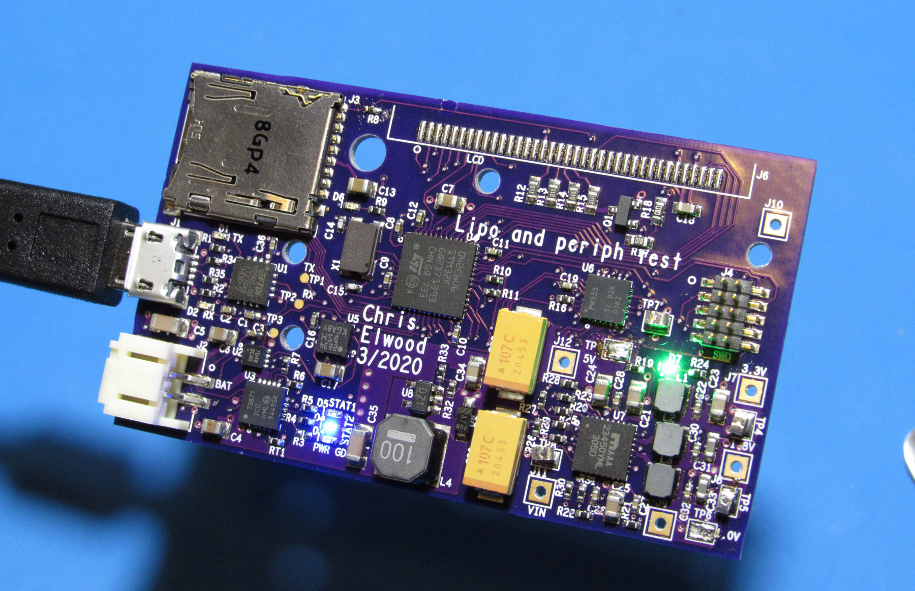
[2/18/2019] The goal of this project is to build a device which can run Linux using a NXP i.MX 6ULL processor. Having the ability to integrate this type of processor into future designs will be useful for many projects involving graphical interfaces or networking. However, processors in this class (mostly ARM Cortex-A variants) are much more complex to use than typical microcontrollers. On both the software and hardware sides. I have some experience with embedded Linux from working with Raspberry Pi, but this will be my first time getting into the hardware part of things.